1. Data models

This is the Data models course theme. In this section we introduce concepts for modelling data and language for communicating those models.
[Complete set of notes PDF 870Kb].

1.1. Introduction

Databases are pervasive in modern society. So many of our actions and attributes are logged and stored in organised information repositories, or Databases
[Section notes PDF 227Kb].

1.1.01. Databases

  • Where do we come into contact with databases?
  • Supermarket inventories/EPOS
    • Supplies, shopping habits, store locations, accounts
  • Films (iMDB)
    • Cast lists, shooting schedules, histories, budgets
  • Department
    • Students, courses, staff, payroll

These are all examples of relatively simple databases. All of the information is textual or referential.

1.1.02. New technologies

  • Not just traditional, numeric/textual
  • Research 70s biased
  • Digital media
    • Video servers (atom/bbc/youtube)
  • Multimedia databases
    • Web site, collection of diverse data types
    • Google, AltaVista
  • Stock Exchange
    • Futures, Currency markets, trends
    • Databases comprising not only data, but modelling algortihms
  • Microsoft's WinFS

Databases don't have to store just text. Increasingly Database servers are storing, indexing and delivering rich-media content, explicitly images, audio and video.

Microsoft's next generation File storage system (WinFS) is a relational database. From a user perspective, searching (the process of indexing content by keyword) is already mainstream. Users are moving away from rigid directory structures (files and folders) and towards keyword-tagged content.

1.1.03. Variations

  • Not only in role
  • Size
    • Video server example
  • Complexity
    • Ford Puma™ example
    • Ford staff organised by production line and car
    • e.g. Each staff member answers to a 'part' manager (engines, bodyshell, chassis) and a 'car' manager (Puma, Mondeo, Ka)
  • Expense
  • User profiles and demands

We've seen that databases are used in a variety of contexts. Those roles imply properties of each of the systems. An interlinked text-only database (such as Unix/Linux's MAN pages) will require much less storage than a video archive.

Some databases are perceptually more complex. Ford's staff management model would be represented as a matrix (in this case 2 dimensional). Computers are very good at organising multi-dimensional space.

1.1.04. Definition

  • Embrace diversity
  • Data and semantic
  • Database: related data, implicit meaning
  • Sample/subset of real world
    • real world with bounds
  • Miniworld/Universe of Discourse

A single definition of a database is hard to come by. Dictionary.com defines a database as: a comprehensive collection of related data organized for convenient access, generally in a computer. The Wikipedia definition runs for several pages.

1.1.05. Abstraction

  • Previous lab exercises
    • Problem: reading data from a file
  • Abstraction theme
  • Basis of good OOP and further good P
    • from encapsulation to software component analysis
  • Layering, splitting data from design
    • Solution: grammar (language guide) and data

In some of your previous lab assignments, or practical experience, you may have been faced with the problem of caching information persistently in a file, later to be reloaded.

When writing the data into the file, we are storing more than just that information. We are storing implicitly a design/grammar for that data. That implicit design is evident when accessing the file with a naive interface. If you try to read the data out in a different order, it fails.

A better solution is to split the way the information is stored from the actually information stored.

1.1.06. Data-design divide

  • Left-hand/right-hand divide
  • LHS: Catalog
    • or Meta-data
    • or Intension
    • or Schema
    • i.e. the Design of database
    • Types of data, organisation, constraints
  • RHS: Extension
    • or Snapshot
    • The data itself
    • Information stored in the database
    • Tuples

Database data design divide

1.1.07. DBMS

  • DataBase
  • Management
  • System
  • Collection of programs that enable users to:
    • Define - patterns, boundaries, design
    • Construct - populate to go live
    • Manipulate - runtime changes
  • data in a structured, organised store.

1.1.08. Database Management Systems

  • Properties
  • Data models and independence
    • Requirements
    • Categorisation of Database users
  • DBMS components
    • Architecture

When considering the database systems as a whole, we need to look at all the components, including elements that interact with the DBMS (users, whom we categorise for simplicity).

This course will contain a discussion of the components that make up the system and the way they interact (system architecture).

1.1.09. Models

  • Data models
  • Relational data model (Oracle)
  • Object data model (ObjectStore)
  • Legacy systems
    • Hierarchical data model
    • Network data model

A data model is an invention. It is a construct that allows us to share an understanding of how the system works. As with all good constructs, it's an abstraction; a simplification; a story.

In this course we're going to look at the Relational model, where the database is organised into tables (relationals) and each row (tuple) within that relation is coded (keyed) to allow referencing between the relationals.

The Relational model, inspite of being innovated in the 1970s is still the most popular, underpining mainstream modern databases such as Oracle 10i and MySQL 5.0

As programming languages are becoming increasingly Object orientated, programmers require a means of persistently storing their Objects. Object Orientated Databases (OODBs) exist to fulfil this purpose. OODBs may ultimately replace relational databases, but it's not clear at this stage when.

1.1.10. Other properties

  • Beside Data model
  • Number of users
  • Number of sites
  • Cost
  • Types of access paths
  • Generality, or inversely specificity

MySQL is a highly general database system, in that it supports many different designs. My mobile phone address book is a highly specific database system and as such is not easily extensible.

1.1.11. Independence

  • Based on File processing
  • Data definition implicit in
    • Data
    • Application program
  • Example of one specific database
  • Structure embedded into access program
    • Coursework code re-use example

Earlier I made mention of this problem. Databases tie into the wider Software Engineering field. Within Software Engineering, post-development issues of code re-use, maintenance, future evolution etc. necessitate a logical flexible approach to program design. Databases are such an approach. In order to store information in a database you invest a small amount of time in explicitly structuring it, however you then get things like flexibility (data independence etc.) for free.

1.1.12. Program-data independence

  • General databases
    • Separate Data definition and data
    • Catalog/meta-data & tuples
  • Data format/structure stored separately
  • Program-data independence (e.g. Y2K)
    • Changes in data format
      • Alter data (tuples)
      • Alter grammar (catalog/meta-data)
    • We actually split program-data independence into:
      • Logical
      • Physical
    • ...more in a second

1.1.13. Program-operation independence

  • In object-orientated databases
    • Objects consist of attributes and operations
    • Operation defined by
      • Header/Interface/Prototype or Signature
      • Implementation
    • Program-operation independence
      • Implementation change hidden from user
    • Collectively data abstraction

1.1.14. Logical and physical program-data independence

  • Three tier data-model diagram
  • Mappings, Data independence
    • Logical
      • between conceptual and external
      • changes to conceptual without changing
        • external schemas or application programs
    • Physical
      • between internal and conceptual
      • changes to internal without changing
        • conceptual or external schemas

    database three tiers external conceptual internal

1.1.15. DBMS Requirements

  • DataBase Management System
    • Abstraction (i.e. program-data independence)
    • Conceptual representation (data models)
    • Multiple views and User Interfaces
    • Data sharing and transaction processing
    • Access restriction
    • Redundancy removal/optimisation
    • Persistent storage (Program objects) & Integrity
    • Relationship management & Inference
    • Backup and recovery

Here's a summary of what we need from a DBMS

1.1.16. Database Users

  • Database as 1y resource, DBMS as 2y
  • Database administrators (DBA)
  • Database designers
  • End users
    • Naïve - canned transactions e.g. bank/airline
    • Sophisticated - engineers, scientists, query editors
    • Stand-alone (personal databases/MS Access)

1.1.17. Results of use

  • Knock-on effects of database approach
  • Enforcing standards
  • Reduced Development time
  • Adaptive to change (design changes)
  • Up-to-date information (live database)
  • Economies of scale
    • centralising commonly required resources

...and this is what you get for free. These are the consequences, largely positive, of adopting a database approach to an information storage problem.

1.1.18. Design side

  • Meta-data
    • Database schema, intension
    • Data Model
    • Left hand side of database divide
  • Schema diagram
  • Entity-relationship (ER diagrams)
  • UML diagrams

Database Schema diagramDatabase Entity Relationship diagram

1.1.19. Data side

  • Data, under the column heading
  • Less easy to look at (volume issue)
  • Fundamentally less interesting (more specific)
  • Variety of tools for looking at it:
  • Here's what a snapshot looks like:

Database data snapshot example

1.1.20. Data model

  • Data model
    • Structure of the database
    • Collection of basic operations
    • Collection of behaviours/user defined operations
  • Dependent on level of abstraction
  • Tier diagram
    • External (user views)
    • Conceptual*
    • Internal

1.1.20. General data model terms

  • Entity
  • Relationship
  • Attributes
  • Keys

What follows here is an introduction to the terms which make up the language that we use to describe data models.

1.1.21. Entity

  • Selected from real world
  • Populate Miniworld/UoD
  • Entity is an approximation
  • Two elements: Entity types and sets
  • Collection of attributes
    • Object similarity, classes as entity types
  • Entities inter-relate

Database entity types and sets

1.1.22. Attributes

  • Data type, domain
  • Simple or composite
  • Single or multivalued
  • Stored or derived
  • Null

1.1.23. Keys

  • Mechanism for unique identification
  • Uniqueness constraint
  • Strong and weak entities
  • Key attribute
  • Composite keys
  • Multiple keys

1.1.27. Relationships

  • Types and Sets
  • Participation by Entities
  • Degree - e.g. binary
  • Cardinality ratios - e.g. 1:1, 1:M
    • Determine occurrence
  • Tuples example
    • Foreign keys

Database Relationship types and sets

1.1.28. Database architecture

  • Client-Server
  • Distributed databases
    • Fragmentation by attribute/tuple/relation
  • Language and description
    • Storage Definition Language (SDL) DESIGN
    • Data Definition Language (DDL) DESIGN
    • View Definition Language (VDL) DESIGN
    • Data Manipulation Language (DML) DATA
      • High level, can be embedded but precompiled
      • Procedural, record-at-a-time, requires high level support

Database client-server model

1.1.29. Structured Query

  • Structured Query Language (SQL or SEQUEL)
  • Success of relational databases
    • Developed for SystemR at IBM
  • ANSI standardised
    • SQL1 or SQL-86, ongoing extension
  • SQL2 or SQL-92, current version
  • SQL3 (1999), SQL2003
  • DDL, DML(low-level) and VDL

1.2. Data models

A data model is a model that describes in an abstract way how data are represented in a business organization, an information system or a database management system - Wikipedia
[Section notes PDF 310Kb].

1.2.01. Introduction

  • Relational model
  • Abstract operations on relations
    • Set theoretic operations
    • Relational-specific operations
  • Basic algebra operations
    • Union, Intersection, Difference
    • Cross product

1.2.02. Relational model

  • Table as relation
  • Row as tuple
    • real world entity or relationship
    • fact
  • Column as attribute
    • Domain

Schema-state divide for Relational schema

The concept of a relation is abstract, therefore we have a number of different ways of visualising it.

1.2.03. Relation

  • Relation schema R(A1, A2, A3.. An)
    • Design side
    • Assertion/declaration
  • Relation state
    • Data side
    • set of n-tuples
      • each one an ordered list of values
        • 1NF: each value is atomic, no composite/multivalue

    Data-design divide

1.2.04. Abstract operations

  • Database lifecycle
    • design, populate, evolve
  • Insert
    • tuple (a1,a2,a3…an)
  • Delete
    • tuple (a1,a2,a3…an)
  • Update (or modify)
    • tuple (a1,a2,a3…an)
    • attribute to change, new value

Insert, update and delete

All the operations described in the next few sections are abstract. We're going to see how valuable they can be in processing real world data later.

1.2.05. Basic algebra

  • Two categories
    • Set theoretic operations
      • Union, Intersection etc.
    • Relational specific
      • Select, project and join

    At this stage we're talking about set theoretical operators on the Relational model, not SQL instructions which confusingly have identical names and only similar behaviour.

1.2.06. Select operation

  • SELECT a subset of tuples from a relation
    • Uses selection condition
      • Evaluate each tuple to true of false
      • False tuples discarded
    • Sigma (s)
    • output = s(cond)(input_relation)
    • Relation schema: R(output) = R(input_relation)
    • Commutative

1.2.07. Project operation

  • PROJECT a subset of attributes for all tuples from a relation
    • Pi (p)
    • p<attribute list>(R)
  • If sublist is only non-key attributes
    • might get duplicates
  • Removes duplicates
  • Attribute list:sublist example

The result set of the operation is itself a relational. That output relation will contain the same number of rows as the input, however it may contain a different number of columns; fewer if a subset of attributes is projected; more if derived or aggregated attributes are included.

1.2.07. Sequences of operations

  • Select followed by projection
  • Area clipping: rows then columns
  • p<attr list>
    (
    s(select_cond)(R))
  • Rename operation (r)
    • Renames attributes list2 from list1
    • r(new_attr_names)(R)

Select, Project and composite abstract operations

1.2.08. Rename operation

  • Attribute renaming only
    • Cannot alter domain, or add/remove attr
  • Rename operation (r)
    • Renames attributes list2 from list1
    • r(new_attr_names)(R)
  • Implicit renaming
    • Order dictated by relational schema

1.2.08. Set Theoretic

  • Binary operation: two relations
    • Sets of tuples
    • Union compatibility (same attributes)
  • Union (R u S)
  • Intersection (R n S)
    • Commutative (R u (S u T) = (R u S) u T)

Relation Union operation on compatible relations

1.2.08b. Set difference

  • Set difference
    • Non-commutative (R-S != S-R)

Set difference example

1.2.09. Cross product

  • Cartesian product of two relations
  • R x S
  • Also known as
    • Cross product
    • Cross join
      • Cross product diagram
    • Introduction to complexity
      • Computationally explosive

    colour-coded cross product of two relations

1.2.10. Relational algebra/model notation

  • Relational schema R(A1, A2,…,An)
  • Relation state r or r(R)
    • Set of unordered tuples
    • r = {t1, t2,…,tn}
  • Each n-tuple is an ordered list of values
    • t = <v1, v2,…,vn>
  • ith value in t = vi called t[Ai]
  • r(R) subset of (dom(A1) x dom(A2)... x dom(An))

1.2.11. Constraints

  • Domain constraint
    • For all v in t of r(R)
      vi is an element of dom(Ai)
  • Entity constraint
    • K = SKmin
    • t[K] != null
  • Key constraint
    • Superkey SK as identifying subset of attributes
    • t1[SK] != t2[SK]

1.2.12. Referential integrity

  • Given two relations R1 and R2
    • R1 contains a foreign key (FK) that references
    • A primary key (PK) in R2
      • R1 referencing relation, R2 referenced relation
    • Shared domains: dom(FK) = dom(PK)
    • Foreign exists: t1 in r(R1), t2 in r(R2)
      • t1[FK] = t2[PK] || NULL

1.3. Joins

In this lecture we look at...
[Section notes PDF 233Kb].

1.3.01. Introduction

  • Recap: pulling data out of individual relations
    • By row, by column
    • Select and project
  • Access across multiple relations
  • Miniworld approximation
    • Fragmenting entities by cardinality
    • Tuples as entity fragments
    • Relationships within relations
  • Joins
  • Join types (condition and unmatched)

1.3.02. Access across relations

  • Relational model allows multiple relations to exist within one database schema
  • Relations can be accessed individually or together (joins).
  • Referential integrity
    • Relations relating
  • Pulling data out of single relations
    • Select and project
  • Pulling related data out of
    • Multiple relations using Join

1.3.03. Miniworld approximation

  • Universe of Discourse, or Miniworld
  • Miniworld is an incomplete model of the real world
  • The relational data model as a model for the miniworld
  • Approximation
    • Separate and distinct entities
    • Single complex entities
    • Separate related entities
    • Cardinality of relationships
  • Each relation made up of attributes
  • Values can be used as references

1.3.04. Pointing mechanism

  • Relation has a Primary key
  • Tuple contains Primary key value
  • Foreign keys
    • Tuples can contain a reference to another relation's Primary key
  • Just numbers

Relational model foreign key example

One number identifies a single tuple in one relation (local), one number identifies a single tuple in another relation (foreign).

1.3.04b. Pointing mechanism example in C

  • C programming language
  • Memory addresses, or pointers
    int a=0;
    int b=0;
    a = &b;
    
  • a points to b

relational foreign key C programming example

In databases, typically done with unique identifiers (IDs) rather than memory addresses.

1.3.04c. Pointing mechanism with structures

  • Foreign key importing
    typedef struct car
    {
      int ID;
      char[] make;
      char[] model;
      char[] derivative;
      int optionID;
    } car;
    
    typedef struct option
    {
      int ID;
      char[] name;
      int price;
    } option;
    
    car c;
    option o;
    //...data structure populating
    c.optionID = o.ID;
    

Relational foreign key example in C with Structures

1.3.05. Relational cardinality

  • 1:0 relationships
    • Single entity
    • Uniquely indentifiable
    • Candidate keys
    • Primary Key
  • 1:1 relationships
    • Two entities, A and B
    • 1 A relates to 1 B and vice versa
  • 1:N relationships
  • M:N relationships

1.3.06. Relationships in the relational model

  • Two relations, A and B
  • A side, B side, 1 side, N side
  • 1:1 relationships
    • Key can go on either side

Relational model 1 to 1 relationships

  • 1:N relationships
  • Key cannot go on 1 side
  • Has to go on N side

Relational model 1 to N relationships

  • M:N relationships
    • Nowhere obvious for the key to go
    • Create new pairing relation

1.3.07. Joins

  • Phase change, different point in lifecycle
  • Join operation
    • Combines related tuples, conditionally
    • From two relations
    • Into single tuples
  • Allows processing of relationships
  • Among multiple relations

1.3.08. Joins, canonical algebraic form

  • Conditional (on join condition)
    • Only combines tuples where true
  • Cartesian product (conditionless)
    • example of conditionless join
    • all tuples combined
    • R ⋈true S
  • ⋈, Binary operator
    e.g. R ⋈<join_condition> S

1.3.09. Join equivalence

  • Equivalent to sequence
    • Cartesian product (X)
    • followed by Selection (s)
  • ACTUAL_DEPENDENTS =
    sSSN=ESSN(EMPNAMES X DEPENDENT)
  • or
  • ACTUAL_DEPENDENTS =
    EMPNAMES ⋈ SSN=ESSN(DEPENDENT)

1.3.10. Join types (condition)

  • Theta: Ai q Bj
    (A from R, B from S)
    • q is comparison operator
      =,<,>,!=,>=
    • Ai and Bj share the same domain
  • Equi: Ai = Bj
    • Theta join where q is =
  • Natural: Ai and Bj are the same attribute
    • in two separate relations (name and domain)
    • * denotes natural join
    • e.g. EMPNAMES * DEPENDENTS

Relational join example, equijoin

1.3.11. Join types (inner and outer)

  • Inner joins
    • not the only joins
    • eliminate tuples without a matching counterpart
    • i.e. tuples with a null value for the join attribute are discarded

Relational Inner join demonstration

1.3.12. Outer joins

  • Outer joins control what's discarded
    • Keep unmatched tuples in either
      • Left, right, or both relations
      • Left, right of full outer join correspondingly

    Relational demonstration of Outer joins

1.4. ER diagrams

In this lecture we look at...
[Section notes PDF 75Kb].

1.4.01. ER Diagrams and Relational mapping

  • Design communication techniques
    • ER diagrams
    • ER to relational mapping
  • Entities to Objects
  • Type Inheritance
    • EER diagrams
    • UML
  • Web DB Integration

1.4.03. Design in the modern context

  • Team based development
  • Documentation
    • Value of design over description
  • DB sketching (left hand side)
    • Concept more important than perfection
    • Design iteration
  • Mini-world as approximation
    • Categorisation to create entities
    • Verb’ing to create actions/relationships

1.4.04. Database Left:right divide

  • Design
    • Catalog, Meta-data, Intension, or Database schema
    • Entity type
    • Relationship type
  • State
    • Set of occurences/instances, Extension, snapshot
    • Entity set
    • Relationship set

Entity and Relationship, types and set in the context of the database design and data divide

1.4.05. Basic ER diagram

  • Typically part of a system
  • (Strong) Entities
    • Product
    • Customer
    • Payment
  • Relationships
    • Sale

simple entity-relationalship (ER) diagram

1.4.06. Mapping ER to Relation DB tables

  • Intuitive mapping
    • Entities as tables
    • Attributes as columns
  • Relationships are more difficult
  • Key sharing mechanism
    • Foreign key references primary key
  • Where to put the foreign key forms the intuitive guide to the rest of
    the mapping

1.4.07. ER to Relational mapping

  • Step-by-step approach
  1. Strong entities
    • Create relation including (simplified) attributes
  2. Weak entities
    • Create relation inc. attr, foreign/pri key of owner
  3. Binary relationship S:T, 1:1
    • Choose relation, say S (with total participation) and inc. foreign/pri
      key of T
    • inc. relationship attributes

1.4.08. Cardinality

  • Specifies number of relationship instances a single entity can participate in
  • S:T (1:1)
  • An entity from table S can is related to one, and only one entity from table T
  • 1:1, 1:N, N:M
    • DEPARTMENT : EMPLOYEE
    • EMPLOYEE : EMPLOYEE
    • PROJECT : EMPLOYEE

1.4.09. ER to Relational mapping

  1. Binary relationship 1:N
    • Choose relation T (N-side) inc. foreign/pri key of S
  2. Binary relationship M:N
    • Create relation, inc. foreign/pri keys of S&T
  3. Multivalued
    • For each mv_attr, create new relation, inc. foreign/pri key of parent
  4. n-ary relationship
    • Create new relation, inc. all foreign/pri keys of participating
      entities

1.4.10. Participation

  • Participation constraints
  • Existence of an entity dependant upon
    • being related to another entity
    • via relationship type (left hand/design)
  • Total (")/Existence
    dependency (double line)
    • Every student must be in a faculty
    • For every entity in the total set of students
  • Partial ($) (single line)
    • Some students are student_representatives
    • There exists some entity(s) within the set of all…

1.4.11. Library example

  • Library example
  • Entities: Person, Book, Librarian
  • Time-perspective implications

Library example ER diagram

1.5. UML

In this lecture we look at...
[Section notes PDF 86Kb].

1.5.01. UML diagrams

  • Not just one type of diagram
  • ER Entities -> UML objects
  • Adds scope to include methods

a simple UML class

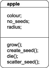
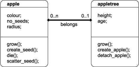
1.5.03. Simple UML relationship diagram

  • Classes
    • Attributes
    • Methods
  • Relationships
    • Participation
    • Cardinality
    • Roles

UML simple relationship diagram

1.5.04. UML inheritance

  • Notion of inheritance
    • Java parallel
    • 'is a' relationships
    • Database Student
      • is a Computer Science Student
        • is an Engineering Faculty Student
          • is a Student
            • is a Person
    • Inheritance hierarchies
  • UML diagrams can be used to show inheritance

UML class diagram, basic inheritance

1.5.05. UML diagram

  • Classes
  • Relationships
  • Inheritance

UML class diagram showing inheritance